5.4 - Recovery Preparation
Module: Recovery Recycling Reclaiming Evacuation and Dehydration
Regulatory verification date: August 9, 2026
Course role: Provides a systematic pre-recovery checklist so that the refrigerant, recovery equipment, recovery cylinder, hoses, and work area are ready before refrigerant removal begins
Learning Objectives
After completing this section, a student should be able to:
- Identify the refrigerant and select recovery equipment that is appropriate for the refrigerant and appliance.
- Explain how refrigerant mixing and cross-contamination can occur and how to prevent them before recovery begins.
- Inspect a recovery machine, including applicable oil and filter checks, before operation.
- Select a suitable recovery cylinder and determine whether it has enough available capacity for the planned recovery.
- Determine when an empty recovery cylinder should be evacuated before use.
- Connect a typical recovery setup correctly and complete the basic safety checks required before starting the recovery machine.
Introduction
A successful refrigerant recovery begins before the recovery machine is started.
The technician must first make sure that:
Correct refrigerant is identified
+
correct recovery equipment is selected
+
equipment is ready
+
correct recovery cylinder is available
+
cylinder has enough capacity
+
hoses are connected correctly
+
work area is safe
Skipping these checks can lead to:
- Mixed refrigerants.
- Contaminated recovery equipment.
- Recovery-machine damage.
- Incorrect hose connections.
- Cylinder overfilling.
- Excessive pressure.
- Refrigerant release.
- Unsafe exposure.
- A recovery operation that cannot be completed correctly.
A useful rule is:
Prepare the entire recovery path before refrigerant begins to move.
Section 5.4 focuses only on pre-recovery preparation. Recovery sequence and recovery-speed methods are developed in Section 5.5 - Recovery Methods and Recovery Speed, while detailed recovery-cylinder rules are developed in Section 5.6 - Recovery Cylinders.
Key Concepts
1. Identify the Refrigerant First
Before connecting recovery equipment, determine what refrigerant the appliance is expected to contain.
Useful identification sources include:
- Appliance nameplate.
- Equipment service label.
- Manufacturer documentation.
- Previous service records.
- Refrigerant identification equipment when contamination or incorrect charging is suspected.
Do not choose a recovery machine or cylinder merely because:
the service fittings appear to fit
or because:
the pressure seems familiar
Different refrigerants can operate at similar pressures under some conditions.
A pressure-temperature comparison can be useful as a screening tool, but it should not be treated as conclusive identification when refrigerant identity is uncertain.
The correct sequence is:
Identify refrigerant
→ confirm equipment compatibility
→ select recovery cylinder
→ connect recovery setup
2. Confirm the Refrigerant Is Compatible With the Recovery Equipment
Recovery equipment must be suitable for the refrigerant being removed.
Before use, check:
- Refrigerant compatibility.
- Pressure rating.
- Applicable equipment certification.
- Manufacturer-approved refrigerants.
- Whether the refrigerant is flammable or requires specially rated recovery equipment.
- Hose and fitting compatibility.
A recovery machine that is appropriate for one refrigerant is not automatically appropriate for every refrigerant.
The equipment-certification framework is covered in Section 5.3 - Recovery Equipment Certification and Service Fittings.
3. Prevent Mixing of Refrigerants
Different refrigerants should not be intentionally mixed during recovery.
Mixing refrigerants can:
- Make the recovered refrigerant unsuitable for direct reuse.
- Complicate or increase the cost of reclamation.
- Contaminate recovery cylinders.
- Contaminate hoses, manifolds, and recovery machines.
- Produce misleading pressure-temperature behavior.
- Create equipment-compatibility problems.
The preparation rule is:
Known refrigerant
→ compatible clean recovery path
→ appropriate labeled recovery cylinder
If the refrigerant identity is uncertain:
Do not mix it with known clean refrigerant
Keep uncertain or contaminated refrigerant separate and follow the receiving facility’s procedure for contaminated refrigerant.
4. Clear Residual Refrigerant When Changing Refrigerant Types
A recovery machine can retain a small quantity of refrigerant after a previous recovery job.
When changing to another refrigerant type, follow the recovery-machine manufacturer’s procedure for:
- Clearing residual refrigerant.
- Self-purging when the machine provides that feature.
- Evacuating the machine when specified.
- Changing or checking filters where required.
Do not assume that disconnecting the hoses makes the recovery machine internally free of refrigerant.
Cross-contamination prevention includes the:
cylinder
+
hoses
+
manifold
+
recovery machine
not only the appliance.
5. Inspect the Recovery Machine
Before recovery, inspect the machine for obvious problems.
Check:
- Power cord and plug.
- Housing and handles.
- Inlet and outlet fittings.
- Valves and controls.
- Pressure gauges or electronic pressure display.
- Hose connections.
- Cooling-air openings.
- Signs of oil leakage where applicable.
- Signs of physical damage.
- Required certification or equipment label.
- Refrigerant compatibility.
Do not operate a recovery machine that is damaged or outside the conditions permitted by its manufacturer.
6. Check Recovery-Machine Oil When Applicable
Not every recovery machine uses a serviceable oil-filled compressor.
Some modern recovery machines use:
oil-less compressor designs
Therefore, the correct rule is:
Check recovery-machine oil only when the machine design and manufacturer instructions require an oil check or oil service.
For a machine with a serviceable oil system, check as applicable:
- Oil level.
- Oil condition.
- Evidence of contamination.
- Required oil type.
- Manufacturer maintenance interval.
Do not add compressor oil to an oil-less recovery machine.
7. Check Filters and Screens
Recovery equipment may use:
- Inlet filter screens.
- Replaceable filter-driers.
- Internal filters.
- Other protective filtering devices.
Before recovery:
- Confirm that required filters are installed.
- Inspect or replace them according to the manufacturer procedure.
- Replace a restricted or contaminated filter when required.
- Use the correct filter arrangement for the recovery machine.
A restricted filter can increase pressure drop and reduce refrigerant flow.
A missing or damaged inlet filter can allow debris to enter the recovery machine.
8. Inspect Hoses and Fittings
Inspect the recovery hoses before connection.
Check for:
- Cuts.
- Cracks.
- Abrasion.
- Damaged fittings.
- Damaged gaskets or seals.
- Loose connections.
- Contamination.
- Pressure rating.
- Refrigerant compatibility.
Use low-loss fittings where applicable.
A hose is part of the pressurized recovery system. A damaged hose should not be treated as a minor inconvenience.
9. Select the Correct Recovery Cylinder
Use a refillable recovery cylinder that is appropriate for the refrigerant and recovery operation.
Do not use a disposable refrigerant container as a recovery cylinder.
Before use, verify:
- Cylinder is intended for refrigerant recovery.
- Cylinder is compatible with the refrigerant.
- Cylinder is in acceptable physical condition.
- Valve condition is acceptable.
- Cylinder contents are identified.
- Cylinder does not contain an incompatible refrigerant.
- Cylinder has enough available capacity.
Detailed cylinder identification, fill limits, markings, and transportation requirements are covered in Section 5.6.
10. Do Not Mix Refrigerants in the Recovery Cylinder
Before connecting the cylinder, determine what is already inside it.
If a cylinder contains:
R-410A
do not add:
R-22
merely because space remains in the cylinder.
The safe preparation principle is:
One known refrigerant stream
→ one compatible recovery cylinder
unless the cylinder is intentionally being used under an approved contaminated-refrigerant handling procedure.
11. Determine Available Cylinder Capacity Before Recovery
The technician should know before recovery begins whether the selected cylinder has enough room for the refrigerant expected to be removed.
Use a scale.
The basic preparation sequence is:
Check cylinder identification and allowed fill information
→ weigh cylinder
→ determine current gross weight
→ determine remaining allowable recovery capacity
→ confirm enough capacity for the job
Do not estimate cylinder capacity by:
- Lifting the cylinder by hand.
- Shaking it.
- Judging only by pressure.
- Assuming an “empty-looking” cylinder is empty.
Pressure does not directly tell how much liquid refrigerant is already in the cylinder.
The detailed weight-based fill calculation is developed in Section 5.6 - Recovery Cylinders.
12. Place the Recovery Cylinder on a Scale
For a typical recovery operation, place the recovery cylinder on a suitable scale before refrigerant begins to enter it.
This allows the technician to monitor:
cylinder weight
during recovery.
The scale is part of cylinder-overfill prevention.
Do not wait until the cylinder feels heavy before checking its weight.
13. Determine Whether an Empty Cylinder Needs Evacuation
An empty recovery cylinder can contain:
- Air.
- Moisture.
- Other noncondensable gases.
If such a cylinder is used without proper preparation, those contaminants can enter the recovered refrigerant.
Therefore, when required by the cylinder condition or equipment procedure:
Empty recovery cylinder
→ evacuate before recovery
This is especially important when the cylinder:
- Has been open to the atmosphere.
- Is known to contain air.
- Has not been prepared for refrigerant service.
- Is required by the recovery-equipment manufacturer to be evacuated before use.
A new or previously prepared cylinder may already be suitable for service. Follow the applicable cylinder and equipment instructions rather than assuming that every cylinder requires the same preparation.
14. Do Not Treat a Cylinder Containing Refrigerant as an Empty Cylinder
A cylinder containing residual refrigerant is not an empty cylinder.
Do not connect a vacuum pump and intentionally remove refrigerant from a cylinder to the atmosphere.
If the cylinder contains:
- The wrong refrigerant.
- Mixed refrigerants.
- Contaminated refrigerant.
manage it through the appropriate recovery, reclamation, or contaminated-refrigerant procedure.
15. Use a Vacuum Pump When Cylinder Evacuation Is Required
If an empty cylinder must be evacuated to remove air and moisture, use an appropriate vacuum pump and follow the cylinder and equipment manufacturer’s procedure.
Do not confuse:
Recovery machine
with:
Vacuum pump
A recovery machine is used to capture refrigerant.
A vacuum pump is used to remove air, moisture, and other noncondensables from an already refrigerant-free volume.
Detailed evacuation and dehydration are covered in Section 5.7 - Evacuation and Dehydration.
16. Connect the Manifold Correctly
For the standard two-access-point recovery setup used in this module:
BLUE hose
→ low-side appliance access
→ left / low-side manifold port
RED hose
→ high-side appliance access
→ right / high-side manifold port
YELLOW hose
→ center / service manifold port
The blue and red hoses allow the technician to monitor low-side and high-side pressures through the manifold.
The center yellow hose becomes the recovery service path.
17. Standard Self-Contained Recovery Connection
For the standard self-contained setup:
Appliance low side
→ blue hose
→ manifold low-side port
Appliance high side
→ red hose
→ manifold high-side port
Manifold center / service port
→ yellow hose
→ recovery-machine INLET
Recovery-machine OUTLET
→ recovery hose
→ recovery cylinder
This is the same basic connection shown in Figure 5.2.1.
The recovery machine supplies the recovery force.
18. Standard System-Dependent Recovery Connection
For the standard system-dependent setup shown in this module:
Appliance low side
→ blue hose
→ manifold low-side port
Appliance high side
→ red hose
→ manifold high-side port
Manifold center / service port
→ yellow hose
→ recovery cylinder
The appliance compressor and/or system pressure provides the assistance needed to move refrigerant.
There is no independent recovery machine in this path.
19. Not Every Appliance Has Two Permanent Service Ports
The two-access-point manifold arrangement is the standard teaching setup used here because it clearly shows both system pressures and the recovery flow path.
However, some appliances—especially small appliances—may provide only:
- A process stub.
- A single service access.
- A temporary service fitting.
Therefore:
Do not interpret the two-port schematic as a federal rule requiring every appliance to have both high-side and low-side service ports.
Use the actual appliance access arrangement and the applicable manufacturer procedure.
Type I access fittings and process stubs are covered later in Module 7.
20. Start With the Correct Valve Positions
Before making the system active:
- Know which valves should be open.
- Know which valves should be closed.
- Verify manifold valve positions.
- Verify recovery-machine inlet and outlet valve positions.
- Verify recovery-cylinder valve selection.
- Follow the equipment manufacturer’s startup procedure.
Do not open valves randomly to “see what happens.”
Incorrect valve positions can:
- Block refrigerant flow.
- Create excessive pressure.
- Move refrigerant in the wrong direction.
- Release refrigerant when a hose is disconnected.
21. Minimize Air Entry and Refrigerant Release
Connections should be made using a procedure that minimizes:
- Air entering the recovery path.
- Refrigerant escaping from the recovery path.
Do not use routine intentional venting as a hose-clearing method.
Use:
- Low-loss fittings.
- Correct valve sequencing.
- Manufacturer-approved connection procedures.
- Appropriate recovery or evacuation methods.
22. Complete a Pre-Recovery Safety Check
Before recovery begins, check the work area and equipment.
At minimum:
- Wear appropriate eye protection.
- Wear gloves suitable for refrigerant service.
- Provide adequate ventilation.
- Keep ignition sources away when required by the refrigerant and work procedure.
- Confirm that the recovery machine is approved for the refrigerant being handled.
- Confirm hoses and fittings are properly rated.
- Keep the recovery cylinder stable.
- Keep the recovery machine cooling-air openings clear.
- Protect electrical cords from damage and wet conditions.
- Follow lockout or electrical-isolation procedures when the service task requires them.
- Review the recovery-machine and appliance instructions before starting.
Detailed refrigerant, pressure, electrical, flammability, exposure, and cylinder safety is developed in Module 6.
Technical and Regulatory Details
1. Recovery Preparation Is a Combination of Regulation and Best Practice
Not every item in a pre-recovery checklist is a separate federal requirement.
It is useful to separate:
Current Section 608 Requirements
Examples include:
- Use applicable certified recovery or recycling equipment when required.
- Observe the venting prohibition.
- Use recovery or recycling equipment according to manufacturer directions unless those directions conflict with federal requirements.
- Reach the applicable recovery or evacuation requirement before opening covered equipment.
Technical and Manufacturer Best Practice
Examples include:
- Checking machine oil when the machine has a serviceable oil system.
- Inspecting inlet filters and screens.
- Evacuating a recovery cylinder that contains air when required by the equipment procedure.
- Inspecting hose seals.
- Checking cylinder capacity before starting.
- Clearing residual refrigerant from a machine before switching refrigerant types.
The federal requirement establishes the minimum legal framework.
The equipment manufacturer’s instructions determine many details of the actual setup and preparation procedure.
2. Manufacturer Instructions Control Machine-Specific Preparation
Current Section 608 rules require recovery and recycling equipment to be used according to the manufacturer’s directions unless those directions conflict with federal requirements.
Therefore, a generic checklist cannot replace the machine manual.
Different recovery machines can differ in:
- Valve arrangement.
- Purge procedure.
- Filter arrangement.
- Oil requirements.
- Allowed refrigerants.
- Maximum pressures.
- Liquid-handling procedure.
- Flammable-refrigerant approval.
The correct approach is:
General recovery principles
+
machine-specific manufacturer instructions
+
current regulatory requirements
3. Preventing Refrigerant Mixing Is an EPA 608 Test Topic
Avoiding refrigerant mixing is a specific recovery concept for Section 608 preparation.
The technician should establish refrigerant identity before connecting the cylinder and recovery path.
A recovery job should not begin with the assumption:
"We will identify the refrigerant after it is in the cylinder."
By that point, a known refrigerant cylinder may already be contaminated.
4. Recovery Equipment Must Match the Refrigerant and Appliance
A certified recovery machine is certified for specified equipment categories and refrigerant conditions.
Before use, verify:
correct refrigerant
+
correct appliance application
+
correct recovery equipment
Do not rely solely on:
- Hose fitting size.
- Machine appearance.
- Previous use on another refrigerant.
5. Flammable Refrigerants Require Special Attention
When the refrigerant is flammable, recovery equipment must be suitable for that refrigerant and the work area must follow the applicable safety procedure.
Do not use a conventional recovery machine with a flammable refrigerant unless the equipment is specifically approved for that application.
Detailed flammable-refrigerant safety is covered later in Module 6.
6. The Recovery Cylinder Must Be Ready Before Refrigerant Moves
Before opening a path to the cylinder, confirm:
correct cylinder
+
correct refrigerant identity
+
acceptable cylinder condition
+
available capacity
+
correct valve connection
If any of these is uncertain, stop and resolve it before recovery begins.
7. Pressure Is Not a Substitute for Weighing the Cylinder
A cylinder containing a saturated refrigerant can show nearly the same pressure over a broad range of liquid fill quantities when temperature is unchanged.
Therefore:
cylinder pressure
≠
reliable cylinder fill measurement
Use cylinder weight for fill control.
The exact maximum fill calculation is intentionally deferred to Section 5.6.
8. Empty-Cylinder Evacuation Is Not the Same as Recovering Refrigerant
Cylinder preparation may require a vacuum pump to remove air and moisture from an empty cylinder.
That process must not be confused with:
recovering refrigerant from an appliance
Recovery captures refrigerant.
Evacuation removes noncondensables and moisture from a refrigerant-free volume.
9. Hose Arrangement Must Match the Intended Flow Path
For the standard self-contained recovery setup:
BLUE → low side
RED → high side
YELLOW center hose → recovery-machine inlet
machine outlet → recovery cylinder
For the standard system-dependent setup:
BLUE → low side
RED → high side
YELLOW center hose → recovery cylinder
The manifold’s right high-side port should not be left unused when the red high-side hose is intended to monitor the appliance high side in this standard setup.
The red hose may cross another hose in a drawing. Hose crossing is a visual-layout issue; the important point is that each hose terminates at the correct physical port.
10. Prepare for the Entire Recovery Operation
Before starting, the technician should be able to answer all of the following:
| Preparation Question | Ready Condition |
|---|---|
| What refrigerant is in the appliance? | Identified with reasonable confidence |
| Is the recovery machine compatible? | Yes |
| Is the machine in serviceable condition? | Yes |
| Does the machine require an oil check? | Checked if applicable |
| Are required filters/screens ready? | Yes |
| Are hoses and seals in good condition? | Yes |
| Is the correct recovery cylinder selected? | Yes |
| Is cylinder contents/identity known? | Yes |
| Is enough cylinder capacity available? | Confirmed by weight |
| Does an empty cylinder need evacuation? | Completed when required |
| Are low/high/service hoses connected correctly? | Verified |
| Are valves in the proper starting positions? | Verified |
| Is the work area safe? | Yes |
| Are manufacturer instructions available/understood? | Yes |
If the answer to a required item is No:
Do not begin recovery yet.
Important Terms
Available Cylinder Capacity
Available cylinder capacity is the remaining amount of refrigerant that can be safely added to a recovery cylinder without exceeding its allowable fill limit.
It is determined by weight, not by cylinder pressure.
Cross-Contamination
Cross-contamination occurs when one refrigerant, lubricant, debris, moisture, or other unwanted material contaminates another refrigerant stream or piece of service equipment.
Inlet Filter
An inlet filter or inlet screen protects the recovery machine from debris entering with the refrigerant.
The exact filter type and maintenance procedure depend on the recovery-machine design.
Low-Loss Fitting
A low-loss fitting is designed to minimize refrigerant release when a service hose or fitting is disconnected.
Recovery Cylinder
A recovery cylinder is a refillable cylinder designed and approved to receive recovered refrigerant.
Detailed cylinder markings and fill rules are covered in Section 5.6.
Recovery-Machine Inlet
The recovery-machine inlet is the connection through which refrigerant enters a self-contained recovery machine from the appliance or manifold service path.
Recovery-Machine Outlet
The recovery-machine outlet is the connection through which refrigerant leaves the recovery machine and flows toward the recovery cylinder.
Service Hose
The service hose is the center hose of a conventional three-hose manifold set.
In the standard recovery setups used in this module:
- System-dependent recovery: center hose goes to the recovery cylinder.
- Self-contained recovery: center hose goes to the recovery-machine inlet.
Figures and Diagrams
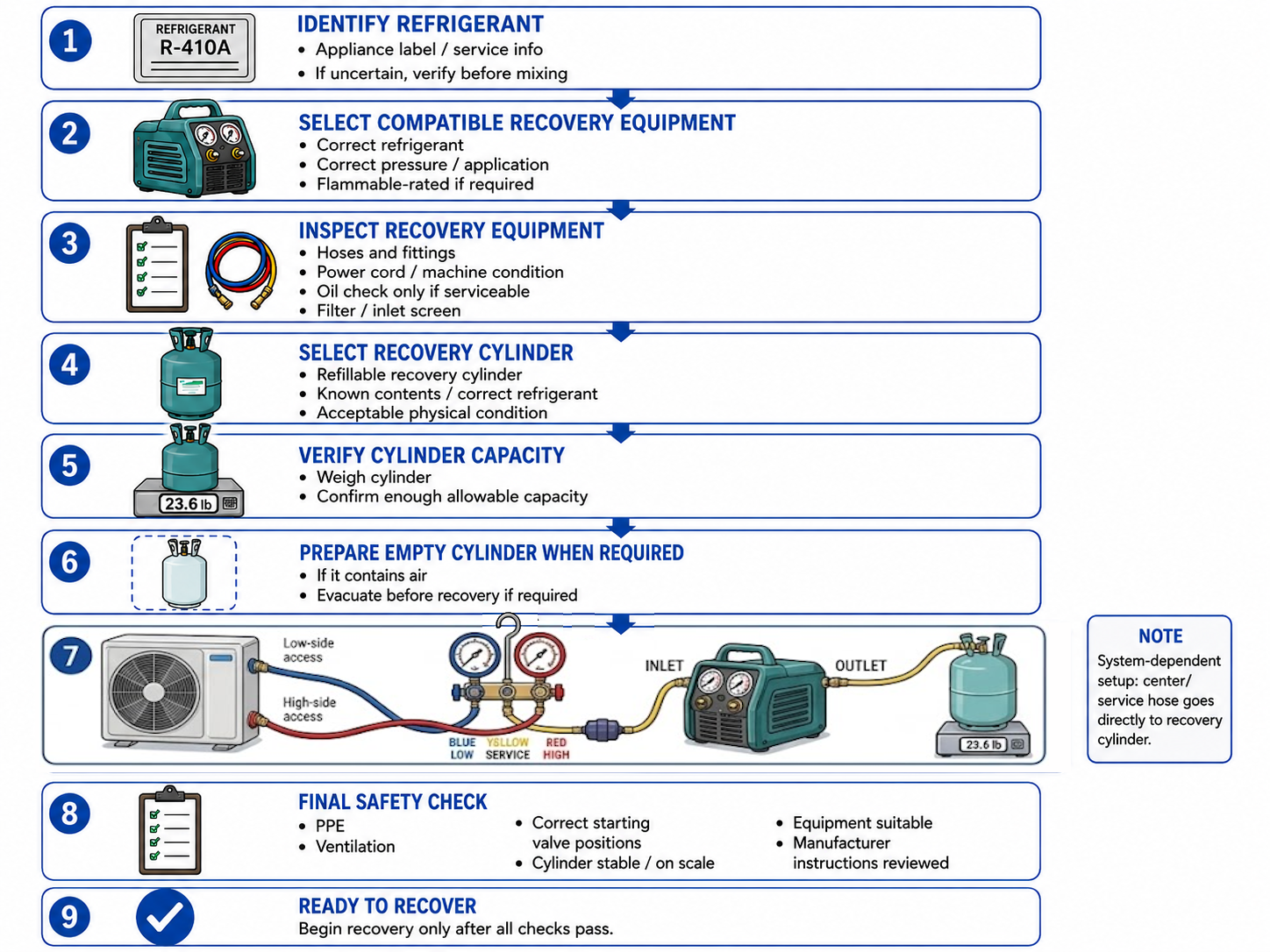
Figure 5.4.1 – Recovery preparation checklist.
AI-generated instructional figure: It may contain visual inaccuracies. Use the accompanying lesson text and cited authoritative sources to verify technical and regulatory details.
EPA 608 Exam Focus
What Students Must Remember
- Identify the refrigerant before selecting the recovery cylinder and recovery equipment.
- Avoid mixing different refrigerants.
- Residual refrigerant in hoses or recovery equipment can cause cross-contamination.
- Check the recovery machine before use.
- Check recovery-machine oil only if the machine design requires oil service.
- Check required filters, screens, hoses, fittings, and seals.
- Use a proper refillable recovery cylinder.
- Know what refrigerant is already in the recovery cylinder.
- Determine available cylinder capacity by weight, not by pressure.
- Put the recovery cylinder on a scale before recovery.
- An empty cylinder that contains air may require evacuation before use.
- Do not treat a cylinder that contains refrigerant as an empty cylinder.
- For the standard manifold setup:
- Blue = low-side / left manifold connection.
- Red = high-side / right manifold connection.
- Yellow = center/service connection.
- In the standard self-contained setup:
- Yellow center hose → recovery-machine inlet.
- Recovery-machine outlet → recovery cylinder.
- In the standard system-dependent setup:
- Yellow center hose → recovery cylinder directly.
- Follow the recovery-equipment manufacturer’s directions unless those directions conflict with federal requirements.
- Use appropriate PPE and ventilation.
- Confirm the machine, hoses, fittings, and recovery cylinder are suitable for the refrigerant.
- A pre-recovery checklist prevents errors before the system is opened to a recovery path.
High-Priority Preparation Sequence
IDENTIFY
refrigerant
↓
SELECT
compatible equipment
↓
INSPECT
machine / oil if applicable / filters / hoses
↓
SELECT
correct recovery cylinder
↓
WEIGH
and confirm available capacity
↓
EVACUATE EMPTY CYLINDER
when required
↓
CONNECT
blue / red / yellow recovery path correctly
↓
CHECK
valves / PPE / ventilation / equipment condition
↓
READY
to begin recovery
Typical Exam Question Patterns
Students may be asked to:
- Identify the first step before connecting recovery equipment.
- Explain why refrigerants should not be mixed.
- Identify what should be checked before operating a recovery machine.
- Recognize that not every recovery machine uses serviceable compressor oil.
- Explain why filters and inlet screens are checked.
- Select an appropriate recovery cylinder.
- Identify why a recovery cylinder should be weighed before recovery.
- Explain why cylinder pressure does not determine remaining fill capacity.
- Determine when an empty recovery cylinder should be evacuated.
- Identify the correct blue, red, and yellow manifold connections.
- Identify the correct self-contained recovery-machine inlet and outlet flow path.
- Identify the system-dependent center-hose destination.
- Recognize the need to follow manufacturer directions.
- Identify basic PPE and work-area checks before recovery.
High-Priority Connection Table
| Connection | Standard Recovery Preparation |
|---|---|
| Blue hose | Appliance low side → low/left manifold port |
| Red hose | Appliance high side → high/right manifold port |
| Yellow center hose — self-contained | Manifold center/service port → recovery-machine inlet |
| Recovery-machine outlet — self-contained | Recovery machine → recovery cylinder |
| Yellow center hose — system-dependent | Manifold center/service port → recovery cylinder |
| Recovery cylinder | Stable, correctly identified, sufficient capacity, on scale |
Common Mistakes and Confusing Points
Mistake 1: Selecting the Recovery Cylinder Before Identifying the Refrigerant
Correct sequence:
Identify refrigerant first
→ then select cylinder and recovery equipment
Mistake 2: Assuming Similar Pressure Means the Refrigerant Is Identified
Different refrigerants can have overlapping pressure ranges.
Use equipment information and proper identification methods.
Mistake 3: Mixing Different Refrigerants Because They Will Be Reclaimed Later
Do not intentionally mix refrigerants during ordinary recovery.
Mixed refrigerant increases contamination and reclamation problems.
Mistake 4: Forgetting Refrigerant Left Inside the Recovery Machine
A machine can retain trace refrigerant after a previous job.
Use the manufacturer clearing or purge procedure when switching refrigerant types.
Mistake 5: Adding Oil to Every Recovery Machine
Some recovery machines are oil-less.
Check oil only when the machine design requires it.
Mistake 6: Ignoring a Dirty or Restricted Filter
Filters protect the machine and affect refrigerant flow.
Inspect and service them according to the manufacturer procedure.
Mistake 7: Estimating Cylinder Capacity From Pressure
Cylinder pressure is strongly related to refrigerant temperature and saturation condition.
Use a scale to determine fill by weight.
Mistake 8: Assuming Every Empty Cylinder Is Ready for Recovery
A cylinder that contains air or moisture may require evacuation before use.
Follow the cylinder and recovery-equipment procedure.
Mistake 9: Evacuating a Cylinder That Still Contains Refrigerant
Do not treat a refrigerant-containing cylinder as an empty cylinder.
Manage the refrigerant properly rather than venting it through a vacuum pump.
Mistake 10: Connecting the Red Hose to the Wrong Manifold Port
For a conventional three-hose manifold:
Blue → left / low
Yellow → center / service
Red → right / high
The hoses may cross visually, but their endpoints must be correct.
Mistake 11: Connecting the Yellow Service Hose to the Wrong Device
For the standard self-contained recovery setup:
Yellow center hose
→ recovery-machine inlet
For the standard system-dependent setup:
Yellow center hose
→ recovery cylinder
Mistake 12: Assuming Every Appliance Must Have Two Permanent Service Ports
The two-port arrangement is a common teaching and service setup.
Small appliances may use a process stub or single access point.
Mistake 13: Starting the Recovery Machine Before Checking Cylinder Capacity
The cylinder should already be:
- Selected.
- Identified.
- Weighed.
- Confirmed to have sufficient capacity.
Mistake 14: Treating Manufacturer Instructions as Optional
Machine-specific operating instructions are part of proper recovery-equipment use.
Follow them unless they conflict with federal requirements.
Concept-Check Questions
Question 1
What should a technician normally determine before selecting a recovery cylinder for an appliance?
A. The refrigerant identity
B. The outdoor air humidity
C. The compressor motor horsepower only
D. The color of the appliance cabinet
Question 2
Why should different refrigerants normally be kept separate during recovery?
A. Mixing refrigerants always increases recovery speed.
B. Mixed refrigerants can contaminate equipment and make reuse or reclamation more difficult.
C. Refrigerant mixtures always become nonflammable.
D. Different refrigerants cannot enter the same type of hose.
Question 3
Which statement about recovery-machine oil is most accurate?
A. Every recovery machine must have its oil changed before every job.
B. Recovery machines never use oil.
C. Oil should be checked or serviced when the machine design and manufacturer instructions require it.
D. Refrigerant oil should always be poured into the recovery-machine inlet before startup.
Question 4
What is the best way to confirm that a recovery cylinder has enough available capacity before beginning recovery?
A. Shake the cylinder.
B. Compare its pressure with atmospheric pressure.
C. Lift it by hand and estimate its mass.
D. Weigh it and compare the current weight with the allowable fill information.
Question 5
When may an empty recovery cylinder need to be evacuated before use?
A. When it contains air or the applicable equipment procedure requires evacuation
B. Whenever the cylinder contains recovered refrigerant
C. Only after it has been filled to its maximum allowable weight
D. Only when the appliance compressor is operating
Question 6
In the standard self-contained recovery setup used in this module, where does the yellow center/service hose from the manifold connect?
A. Recovery-machine inlet
B. Appliance low-side access
C. Appliance high-side access
D. Recovery-machine electrical connection
Question 7
Which manifold connection arrangement is correct for the standard two-access-point setup?
A. Blue hose to right/high port, red hose to left/low port, yellow hose to center
B. Blue and red hoses both to the low-side manifold port
C. Blue hose to left/low port, yellow hose to center/service port, red hose to right/high port
D. Yellow hose to low-side port, blue hose to center, red hose to recovery-cylinder valve
Question 8
Which statement best describes the final preparation step before starting recovery?
A. Open every valve fully regardless of the equipment instructions.
B. Confirm correct connections, valve positions, cylinder capacity, PPE, ventilation, and manufacturer procedure.
C. Disconnect the scale so cylinder weight does not affect recovery.
D. Vent the service hoses to ensure that refrigerant can flow.
Answers and detailed explanations will be provided in
5.12 - Answers and Explanations.md.
Section Summary
Recovery preparation should be completed before refrigerant begins moving.
The basic sequence is:
Identify refrigerant
→ prevent mixing
→ select compatible recovery equipment
→ inspect machine
→ check oil when applicable
→ check filters and hoses
→ select correct recovery cylinder
→ confirm cylinder capacity by weight
→ evacuate an empty cylinder when required
→ connect hoses correctly
→ perform safety check
→ begin recovery
For the standard manifold arrangement:
BLUE
→ low-side access
→ left / low manifold port
RED
→ high-side access
→ right / high manifold port
YELLOW
→ center / service port
For self-contained recovery:
Yellow center hose
→ recovery-machine inlet
→ machine outlet
→ recovery cylinder
For system-dependent recovery:
Yellow center hose
→ recovery cylinder directly
The equipment must be compatible with the refrigerant, the cylinder must have sufficient available capacity, and the setup must be safe before recovery begins.
The next section develops how refrigerant is actually removed and which physical factors affect recovery speed.
See Section 5.5 - Recovery Methods and Recovery Speed.
References
Current Regulatory and EPA Sources
-
U.S. Environmental Protection Agency, Section 608 Test Topics, accessed August 9, 2026.
-
U.S. Environmental Protection Agency, Stationary Refrigeration Service Practice Requirements, accessed August 9, 2026.
-
U.S. Environmental Protection Agency, Refrigerant Recovery and Recycling Equipment Certification, accessed August 9, 2026.
-
U.S. Environmental Protection Agency, Stationary Refrigeration - Prohibition on Venting Refrigerants, accessed August 9, 2026.
-
Electronic Code of Federal Regulations, 40 CFR § 82.154 — Prohibitions, accessed August 9, 2026.
-
Electronic Code of Federal Regulations, 40 CFR § 82.156 — Proper Evacuation of Refrigerant from Appliances, accessed August 9, 2026.
-
Electronic Code of Federal Regulations, 40 CFR § 82.158 — Standards for Recovery and/or Recycling Equipment, accessed August 9, 2026.
Manufacturer Technical References
-
Yellow Jacket, RecoverXLT Operation and Maintenance Manual, recovery-equipment operating and preparation guidance, accessed August 9, 2026.
-
Yellow Jacket, TurboRecover Operation and Maintenance Manual, direct recovery setup and evacuated recovery-cylinder guidance, accessed August 9, 2026.
-
Appion, G5Twin Refrigerant Recovery Machine Operation Manual, cross-contamination and machine-clearing guidance, accessed August 9, 2026.
-
Appion, Recovery Quick Start — Educational Donation Program, recovery-cylinder evacuation guidance, accessed August 9, 2026.
-
NAVAC, NRDDF Recovery Unit User Manual, filter-drier and refrigerant-separation guidance, accessed August 9, 2026.